Instrumentation Division was originally established in 1965, which was expanded by creating Hydraulic Instrumentation Centre under UNDP aid in 1976, and the division is now known as HI division. Under Hydraulic Machinery and Cavitation division, Volumetric Calibration Laboratory was established in 1968 with UNDP aid. Current Meter Calibration facility was established in 1956 and upgraded in 2003 with the latest instrumentation.
Major activities undertaken by various technical divisions in this group are summarized below:
- Instrumentation for collection of data on physical hydraulic models, such as current meters, water level recorders, various types of transducers, signal conditioners, multi- channel data acquisition systems, etc.
- Instrumentation for field data collection on coastal parameters like water level, velocity, wave-height and period, temperature, salinity, depth of water, tides, tidal currents, waves, flow pattern, water samples, thermal mapping, beach samples, etc.
- Computer controlled servo-hydraulic Random Sea Wave Generation (RSWG) systems for wave flumes and basins
- Computer based electro-servo automatic tide generation (ATG) system for tidal models
- Dam Instrumentation for measurement of tilt, settlement, deformations, pore- water pressures and uplift, internal stress, etc.
- Collection and analysis of field data for waves, water levels, currents, temperature, salinity, bathymetry, water quality and sediment characteristics
- Calibration of flow meters and evaluation of performance of valves
- Performance evaluation and tests for voltage fluctuations on bore well pumps
- Assessment of head loss across filters
- Optimisation of pumping system design by water hammer analysis
- Flow measurements for water auditing and assessing the performance of hydropower projects
- Verifying the design of pump house chamber with reference to flow pattern, flow distribution, vortex, etc. and suggesting remedial measures
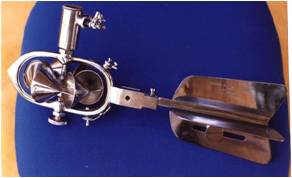
- Servicing and Calibration of conventional rotating element type current meters like cup type, propeller type, pigmy cup, pigmy propeller types conforming to IS 13371/ ISO 3455
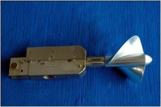
- Calibration of sophisticated stationary element type electromagnetic and acoustic current meters
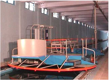
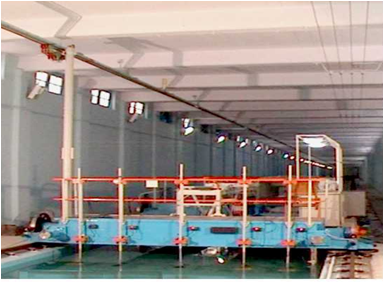
CURRENT METER RATING TROLLY
SALIENT FEATURES OF RATING TROLLEY
v Rating tank 228 m long, 3.66m wide and 2.13m deep
v Electrically driven rating trolley (carriage)
v Speed range 0.01 m/s to 6.0 m/s.
v AC servo motors and drives with PLC for precise speed control .
v PC based data acquisition and processing system using specially developed software .
CAPABILITIES
v Evaluation of drag force / hull resistance on water bodies.
v Servicing and repairs of old current meters .
v Calibration of conventional rotating element type current meters (IS 13371/ ISO 3455) and sophisticated stationary element type viz self recording electromagnetic and ADCP,Contact free radar sensor etc.
METHODOLOGY
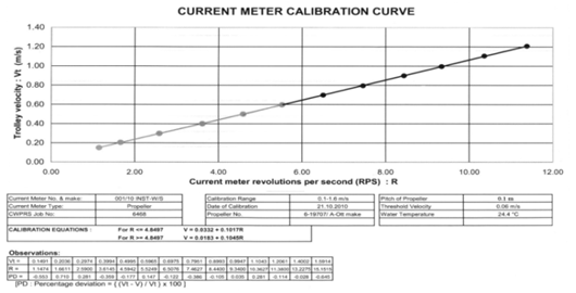
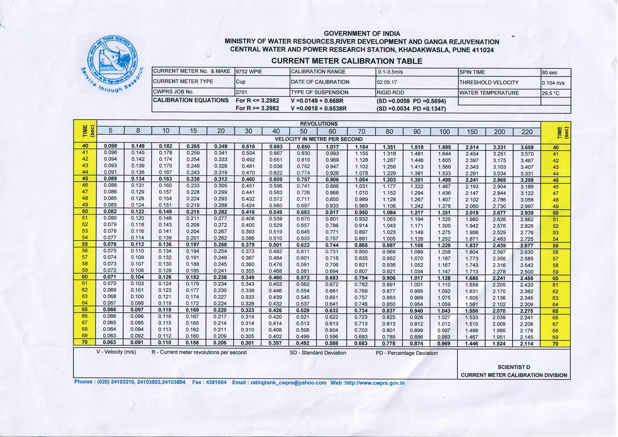
Calibration of current meters in straight open tank (rating tank) is an internationally accepted practice. A new current meter is required to be calibrated so as to establish relationship between its rotational speed and the velocity of flow. Even for old current meter periodical calibration is necessary to account for possible wear and tear of its certain parts. As per IS 13371 it is mandatory to recalibrate the current meters at yearly interval or after 300 hrs of use whichever is earlier During calibration, the current meters are suspended from the carriage and drawn through still water containing in the tank at a number of steady speeds of the trolley. Simultaneous measurements of the speed of the trolley and the rate of revolution of rotor of the current meter are made. The two sets of values are related by one or more equations. The calibration of each current meter is provided in the form of Calibration Table suitable to gauging technique in use.
CLIENTELE
v Central Water Commission
v Central and State Government Departments
v Current meter manufacturers
HYDRAULIC MACHINERY & CAVITATION
The Hydraulic Machinery and Cavitation division has been in service to the nation since 1968. This division has an imprint on major Hydro Electric Power Plants in India for testing the prototype turbines for performance evaluation for periodic health monitoring , RMU , Life Extention(LE) studies.and flow measurement at sites. This division also undertakes calibration of closed conduit flow meters, Testing of Pumps, Hydraulic Model Testing of Pump intakes, CFD Studies for Pump Intakes, Hydraulic designs of pumping systems.
AREAS OF SPECIALIZATION
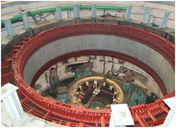
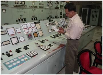
i) FIELD STUDIES OF HYDRO ELECTRIC POWER PLANTS
-Verification of hydraulic performance , Efficiency for Hydro Turbines as per IEC 60041 stipulations for RMU, RLA and LE Studies
-Flow Measurement using various methods as per IEC 60041( Current meters, Ultrasonic (Single/Dual path), Index method and others
 Recommendation for RMU Works
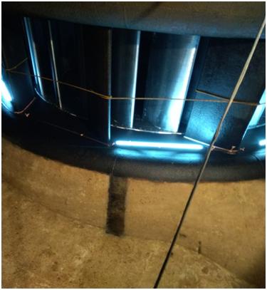
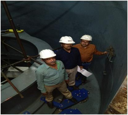
Inspection inside the Turbine Scroll
Case for Flow Measurement Location
Clientele : State Hydro Power Generation Utilities such as MAHAGENCO (Koyna, Bhivpuri , Bhatghar,Veer, Ghatghar, Bhira,Tillari , Vaitarna), KSB( Sholayar, Peringalkuthu), OHPC(Hirakud, Chiplima) and many more.
National Hydro Power Agencies such as NEEPCO(Kopili), NHPC (Loktak, Salal, BhairaSiul),
Private Hydro Power Agencies : VOITH, TATA and etc.
 RMU Tests for 3 X 35MW Loktak HEP , Manipur for NHPC
Site Investigation for Winter-Kennedy
type Flow Measurement
ii) Site testing of large VT & Centrifugal Pumps
• Hydraulic performance of Pumps
• Water Auditing by means of flow measurement and suitable recommendations.
Clientele : TATA, MKVDC Maharashtra and others
.jpeg)
 Flow Investigation on VT Pumps at Site, TATA Power,Trombay
Flow Investigation on VT Pumps at Site, TATA Power,Trombay
Open Channel Flow Measurement for
RMU Works of 18MW Veer HEP
a) LABORATORY FLOW METER CALIBRATION STUDIES
i) Gravimetric Facility :
Circuit Design : Conforms to ISO 4185
Maximum line size : 1200 mm NB
Maximum flow rate : 2.0〖 m〗^3/s
Uncertainty : +/- 0.25 %
Gravimetric system : 100 tonnes
Rated Head : 30mwc
Traceability : National Standards
Calibration of Electromagnetic Flow Meters at 2 Capacity Lab
ii) Volumetric Flow Calibration Facility
Maximum line size : 250 mm NB
Maximum flow rate : 0.25〖 m〗^3/s
Uncertainty : +/- 0.5 %
Traceability : National Standards
Head Loss Test for Heavy Duty Duplex Filter in Gravimetric Laboratory
iii) Head loss across Filters:
Filters of all sizes upto 1200MM are tested for headloss across it
Clientele : Manufacturers of Flow meters across India such as Forbes Marshall, Krone Marshall , ABB, Siemens, Endreuss Hauser and filters for Otoklin, Gujarat Otofilt, Flash Point and more.
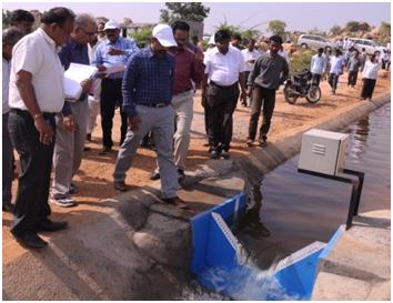
b) FIELD CALIBRATION OF FLOW METERS AND FLOW MEASUREMENT:
• Flowmeters of types such as Electromagnetic, Ultrasonic or any other types are calibrated by secondary method using a pre-calibrated Ultrasonic Clamp-ON type flowmeter of 0.2 Class accuracy.
Clientele Flowmeter users such as NTPC, BHEL, Muncipal Corporations, Usha Martin, Hindalco and many more
Water Auditing at M/s Hindalco ,
Ranchi for Govt. of Jharkhand
c) HYDRAULIC PERFORMANCE OF PUMPS AT LABORATRY
Hydraulic Performance and overload tests on submersible and centrifugal pumps at Laboratories
Pump Test Facility
Hydraulic Performance Test of Submersible
Pump in Pump Test Rig
Maximum line size : 250 mm NB
Standard : IS 9137, 11346 and 325
Maximum flow rate : 0.25〖 m〗^3/s
Maximum head : 50 mwc
Maximum input Power for Pump Motors: 75 kW
Test voltage/ frequency range : 370-500 V, 50Hz/ 0~60Hz
Test uncertainty : + 0.5 %
Current / Power Measurement accuracy : 0.2/0.5 Class
Clientele:
Submersible pumps of Irrigation Department of UP, Rajasthan, Bihar and more for agriculture and water supply needs.
Centrifugal Pumps of private agencies and Public sector undertakings.
Solar Pumps of various Capacity
d) PUMP INTAKE MODEL & WATER HAMMER STUDIES
Pumping system design :
• Optimisation and Water hammer analysis
• Pump sump model studies for improvement of hydraulic conditions and remedial measures
Clientele:
i) Pump Intake Model Studies : Bhopal City Water Supply, MCGB, SAIL, MECON, NPCL, IGCAR,Talcher, Unchahar, Ramgundam, Khargone, Maithon, NathpaJhakri, Kathalguri, Takari, Mhaisal, Parli, Korba, Kota and many more
ii) Pumping System Design : Damodar Valley Corporation, SinnaMadha, Ambora, SAIL etc.
a) CFD STUDIES
• CFD studies for pump intakes using Flow-3D software. Development of Numerical Models are validated with physical model studies for many Govt and Private agencies.
b) CONSTULTANCY STUDIES: Providing Technical assistance in Flowmeter & Pump selection and installation
c) Clientele: Agencies such as DVC, SAIL, NPCIL etc.
RANDOM SEA WAVE GENERATING SYSTEM (RSWG)
Wave generators are used to simulate regular and random sea waves in the laboratory for study of behavior of marine structures in wave flumes and for port layout studies in shallow wave basins.
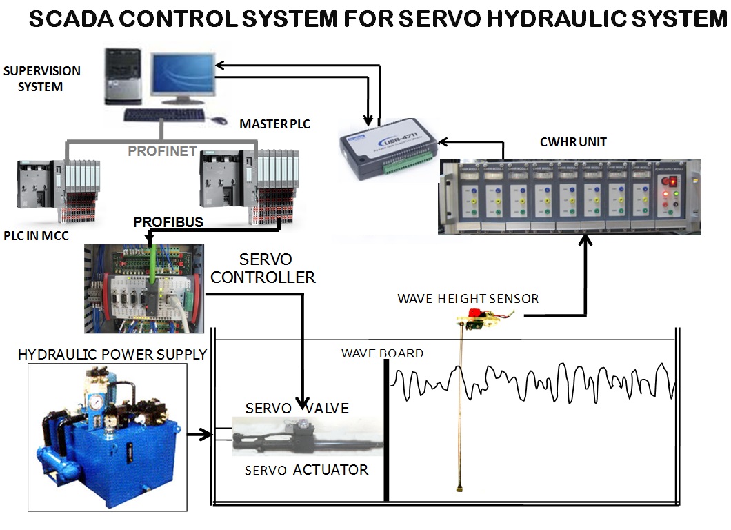
SYSTEM CONFIGURATION
A typical Random Sea Wave Generation (RSWG) System comprises.
• Wave Board Assembly, Hydraulic Power Pack, Servo-actuator, Servo-valve, and electronic servo controller.
• Personal computer based wave generation and data acquisition (Real Time) setup with ADC/DAC modules and multi-channel wave height recorder.
• Software for wave synthesis, wave generation, wave data acquisition, wave height / frequency analysis and tabular/graphical presentation of results.
• Programmable Logic Controller(PLC) and Supervisory Control and Data Acquisition System(SCADA)
METHODOLOGY
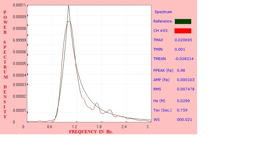
Model simulation of sea wave spectrum derived from wave data collected on site of the port/harbor under study. The field data is analyzed to compute wave energy spectrum. This spectrum is matched with one of the theoretical spectrums derived by scientists’ viz. Scott, Johnswap, Pierson-Moskowitz, Bretschneider etc. The matched spectrum is further synthesized with ‘Smoothed Instantaneous Wave Energy History’ (SIWEH) technique to derive wave train which is reproduced in the model with help of state of art servo hydraulic system driven by PC based Random Sea Wave Generation (RSWG) and Data Acquisition System (DAS) and controlled by PLC and SCADA.
Sea waves are generated in the wave basin with the movement of the wave board in accordance with the driving signal. A driving signal corresponding to desired wave train is generated by Wave simulation software running on Personal computer through Digital to Analog converter and Low pass filter is fed to servo controller. The servo controller drives servo valve to control pressurised oil flow through the servo Actuator which in turn moves the wave board assembly connected to servo actuator and generate random waves in the wave flume/basin. Capacitance type Wave sensors at control points in the basin/flume. Wave data is acquired with help of Data Acquisition System. The acquired wave data is again analysed with ‘Fast Fourier Transform’ (FFT) and ‘Bartlett Window’ technique to compute acquired wave energy spectrum. Iterations of ‘simultaneous wave simulation and data acquisition’ process are carried out to match the theoretical and acquired wave spectrums so as to validate the entire wave simulation process.
RSWG FACILITIES
 |
 |
|
Flumes :120m x 4m x2m
90 x 2m x 1.5m
35m x 11m x 1m (with current
Simulation Facility)
75m x 3m x 2m
|
Basins : Mormugoa
New Mangalore
Kamarajar
Multipurpose Wave Basin
with 3 Direction wave front
|
APPLICATION & USAGE
Various coastal related problems such as design of port layouts and offshore structures are studied using RSWG and DAS and optimized economical solutions are provided such as.
• Wave tranquility studies carried out in Multipurpose Hanger Basin for
- Fishing harbour at Poombughar, Tamilnadu,
- Fishing harbor at Colachel, Tamilnadu
- Development of port facility at village Nandgaon Dist. Thane, Maharashtra
- Development of container terminal off Tekra near tuna, kandla port Gujarat.
- Development of port at Karwar,Karnataka
- Development of port at Jaigad, Maharashtra
• Design marine structures through Hydraulic stability studies carried out in flumes for Vadhwan, Jafrabad, Someshwar etc.
• Design of Break Water for the Development of Fish landing facility at Uvari Village near Kundakulam Nuclear Power Project Tamilnadu.
• Comprehensive hydraulic model studies for various development projects of Mormugao port.
• Breakwater stability studies for extension project Paradip port.
• Harbour layout studies for extension project Paradip port.
• Tranquility studies for satellite port at Kamrajar port.
• Wave tranquility and wave transformation studies for New Mangalore Port, Mangalore.
• Breakwater stability studies for Seabird project, Karwar.
• Simultaneous current and wave studies for Worli-Bandra project.
• Desk and Wave flume studies for design of Breakwater for development of green field port facilities at Dhamankul bay, Jaigad, Maharashtra.
• Desk and Wave flume studies for design of Breakwater for stage II development at fishing harbor at Mirkarwada, Near Ratnagiri, Maharashtra.
• Wave flume studies for design of extension of breakwater at Mul Dwarka, Gujrat.
• Desk and Wave flume studies for Design of Breakwater for proposed development of Harbor for fisheries for deep draft vessels at Sutarpada, Gujarat.
Location Hs from Spectral Analysis
in m. Hs from Wave Height Analysis
in m. Hmax No. of waves
CH #01 2.999 2.887 4.478 119
CH #02 2.991 2.821 4.274 121
CH #03 2.333 2.123 3.018 129
CH #04 2.419 2.245 3.643 121
CH #05 2.223 2.084 2.902 132
CH #06 1.693 1.703 2.285 109
CH #07 1.806 1.794 2.427 102
CH #08 0.738 0.682 1.153 130
Model results in proto scale of wave simulation in the wave basin
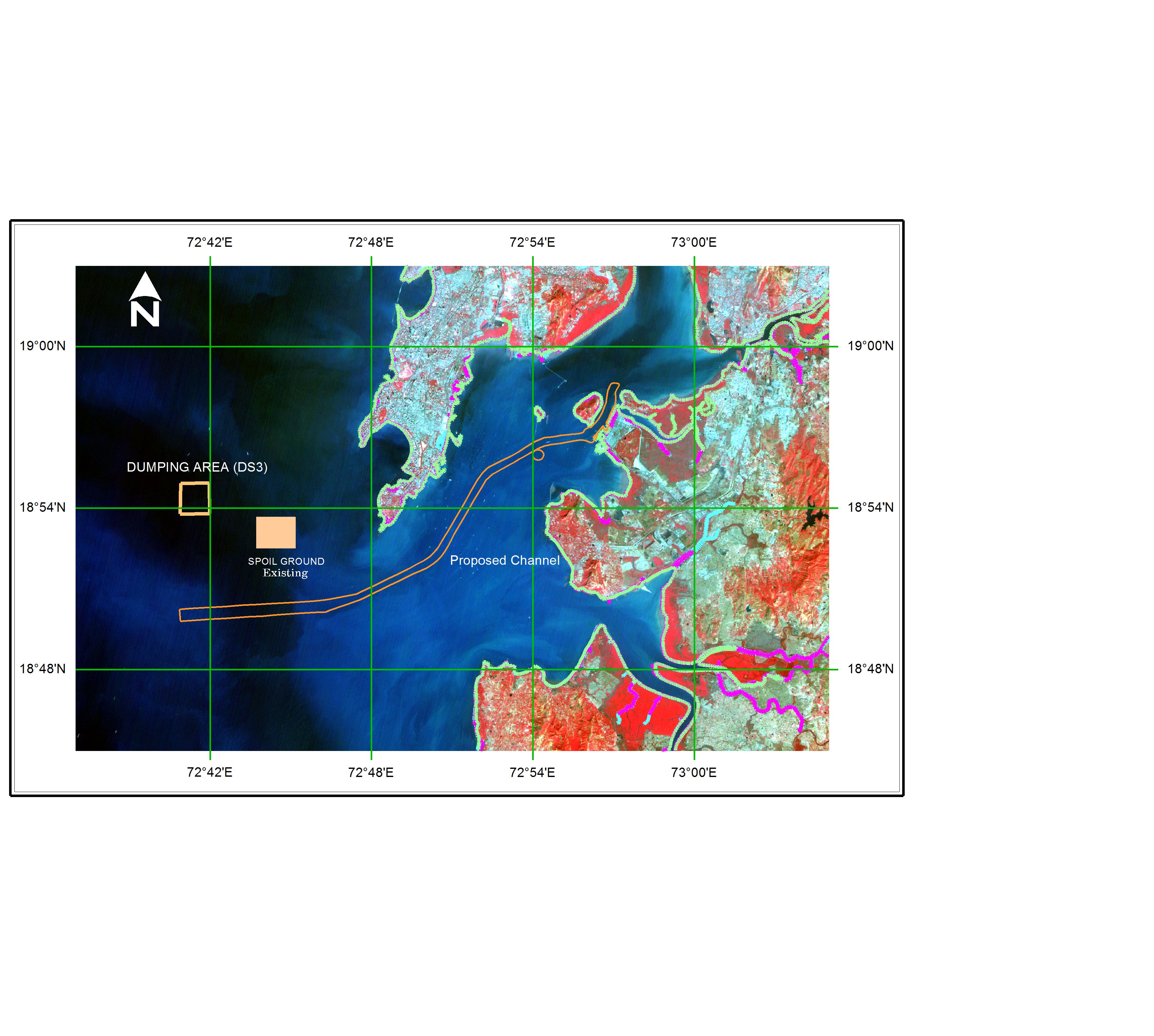
REMOTE SENSING APPLICATION DIVISION
In order to provide viable and economical solutions to various Coastal, River Morphology, Port and Reservoir Sedimentation studies, a need was felt to use the advanced technologies such as Remote Sensing Techniques and Geographical Information System (GIS). Realizing the importance and usefulness of the powerful tool of Remote Sensing in acquiring data and information for development and management of hydraulics and coastal engineering, the Remote Sensing Centre has been established at CWPRS.
FACILITIES
• Remote Sensing Lab with Workstation
• GEOMATICA 2015 software
• A0 Colour Scanner
• Satellite Imageries
Developments of modules in Geomatica software
• Digitization of maps and bathymetry charts necessary for mathematical model inputs
• Development of vector utility function and successfully tested for various projects
Coastal process and shoreline changes
• Tidal data Analysis
• Selection of satellite imageries
• Geometric correction
• Subsetting
• Extraction of land-water boundary contour (shoreline)
• Superimposition of shoreline contours for comparison
Important Projects Carried Out
> M/s JNPT, Mumbai
> M/s JSW Infrastructure limited (JSWIL) Thane, Maharashtra
> ONGC Odalarevu, Andhra Pradesh
> Trombay Power Generating Station, Mumbai
> Kudankulam NPP, Tamil Nadu
River morphology
• Selection of satellite imageries
• Geometric correction of imageries and toposheet
• Subsetting of Area of Interest
• Extraction of bank lines and channel lines
• Superimposition of bank lines and channel lines for comparison
Important Projects Carried Out
> Rivers Brahmaputra, Gandak , Ganga , Mahanadi, Narmada, Kosi, Damodar
Reservoir Sedimentation
• Selection of appropriate period for analysis
• Selection of satellite imageries
• Interpretation and analysis of digital imagery
• Estimation of water spread area
• Estimation of reservoir sedimentation
Important Projects Carried Out
> Reservoirs like Khadakwasla, Jayakwadi, Sriram Sagar, Bhatghar, Ujani, Mula,
Panshet, Bhandardara, Srisailam, Donkarya, ,Krishnarajasagar